1. Overview
"Wind Turbine Tower Foundation Design Software (WTF)" is one content part of "CFD Wind-power Software Series" which is a software package for wind power industry developed by China Hydropower Engineering Consulting Group Co. in conjunction with the Beijing-Millennium Engineering Software Technology Co., Ltd… It is based on "Design regulations on subgrade and foundation for wind turbine generator system", and plays an important role of unifying the Wind Turbine Tower Foundation Design.
2. Characteristics
◇Coordinate with and augment "Design regulations on subgrade and foundation for wind turbine generator system"
◇Calculate speedily, improves the efficiency and reduces the cost of design
◇Promote the standardization of wind turbine foundation design for wind farm projects in China
◇Adjust pile arrangement flexibly, so as to coincide with the actual engineering design
◇ Friendly interface, easy and intuitive operation, easy to grasp quickly
3. Reference
◇"Design regulations on subgrade and foundation for wind turbine generator system"
◇ "Technical code for building piles foundations" JGJ 94
◇ "Code for design of chimneys" GB 50051 ◇ "Code for design of building foundation" GB 50007
◇... ...
4. Main Function Modules
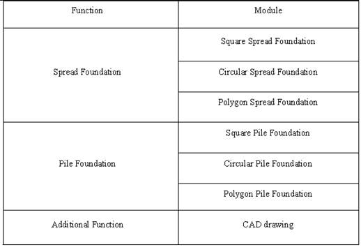
4.1 Calculation Process - Spread Foundation
Take the case of Circular Spread Foundation:
There are several conditions for calculation, including the normal condition, the extreme condition, the frequent earthquake condition and the rare earthquake condition. The calculation can proceed under not only multi-conditions, but also a separate condition.
Complete the process of calculation as follows. Software operation flowchart is as follows:
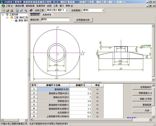
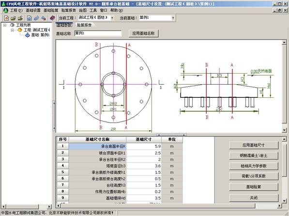
4.1.1 Foundation Size Specification
4.1.2 Geotechnical Parameters Specification
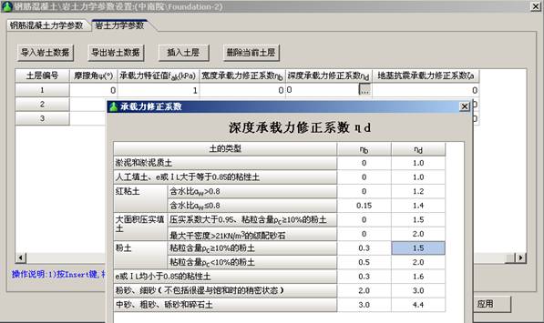
The correction coefficient of subgrade bearing capacity, the depth correction coefficient of subgrade bearing capacity and the width correction coefficient of subgrade bearing capacity in the geotechnical parameters will be obtained from looking up the table which is in accordance with "Design regulations on subgrade and foundation for wind turbine generator system".
4.1.3 Related Parameters Specification of Wind Turbine
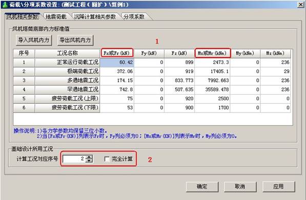
(1) When Fx, Fy, Mx and My are provided by the wind turbine manufacturers, user can input the parameters follow the tips. When Fr and Mr are provided (instead of Fx, Fy, Mx and My), user has to input the parameters Fr and Mr (as seen in red frame 1).
(2) If user chooses "complete calculation" in red frame 2, the calculation will proceed under all conditions. If user cancels "complete calculation" in red frame 2, the calculation will proceed under a separate condition.
(3) Earthquake load will be calculated in the "earthquake load" interface, so there is no need to put it in this blank.
4.1.4 Earthquake Load Calculation Specification
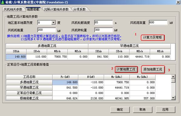
Put these parameters in the relevant blanks, which are earthquake intensity, hub height, weight of turbine tower and weight of rotation. Click the button in red frame 1, and the physical quantities under earthquake condition will be calculated. Then click the button in red frame 2, the characteristic values of load under normal and earthquake condition will be obtained. Finally, click the button in red frame 3, all the results can be filled in the relevant blank of 4.1.3
4.1.5 Settlement Calculation and Partial Safety Factor Specification
Both of them can be chosen and inputted according to "Design regulations on subgrade and foundation for wind turbine generator system", moreover, user can modify the value of partial safety factor.
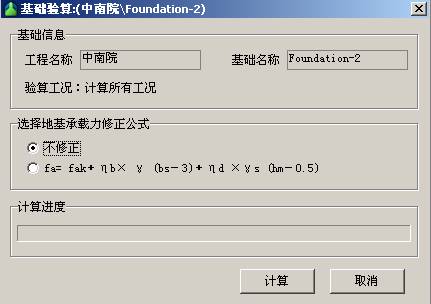
4.1.6 Calculation and Reinforcement Bars Specification
After finishing the processes of 4.1.1 ~ 4.1.5, click the button of "calculation", and the calculation will get under way. If user chooses "no amendment" in the pop-up window, the results will be more secure.
The first pop-up interface is "bottom-foundation reinforcement". In accordance with "Design regulations", reinforcement area must be larger than 2500 mm2 and reinforcement ratio bigger than 0.2% for each meter of reinforced concrete foundation.
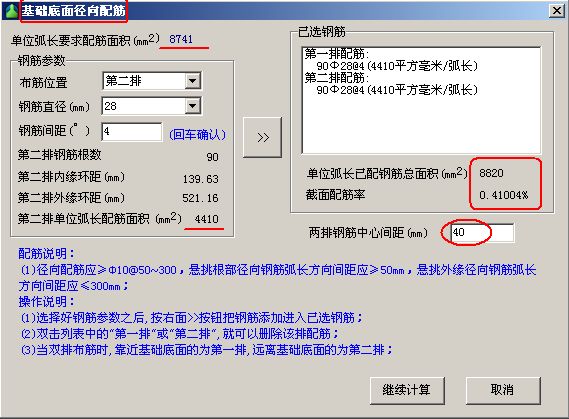
The second pop-up interface is "top-foundation reinforcement", with the proceeding of calculation. The operating steps are equal to "bottom-foundation reinforcement".
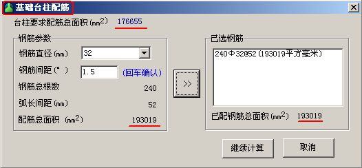
The last pop-up interface is "pillar reinforcement". The operate steps are ditto, but reinforcement ratio must be bigger than 0.4%.
Thus, based on a calculation completed, user can view the report.
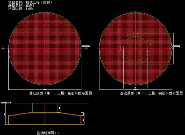
4.1.7 CAD Drawing
After the completion of the previous calculation, click [draw] on the menu, reinforcement drawing of the foundation can be generated.
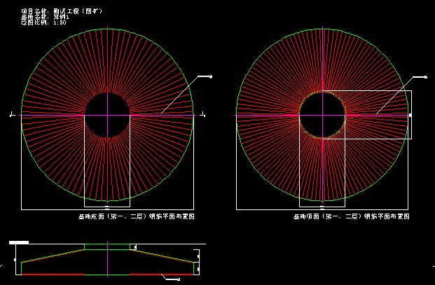
4.1.8 Supplementary Specification
The software operation of square and polygon spread foundation is similar with the circular. However, the reinforcement of Square Spread Foundation is orthogonal, and the reinforcement of circular or polygon foundation is circumferential-diametric.
4.2 Calculation Process - Pile Foundation
Take the case of Circular Pile Foundation. Software operation flowchart is as follows:
4.2.1 Parameters Setting Specification
The content of 4.1.1-4.1.6 is also suitable for pile foundation.
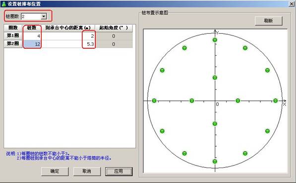
4.2.2 Pile Layout Specification
Click the blank beside "pile number", the system will pop pile interface, as follows:
4.2.3 Supplementary Specification
The software operation of square and polygon pile foundation is similar with the circular. Orthogonal reinforcement is used in all of them, as follows: